Die Casting Porosity Causes and Solutions - Part 1
- Hill and Griffith

- Apr 12, 2018
- 3 min read
By Tim Cowell, Hill and Griffith Company, Technical Director
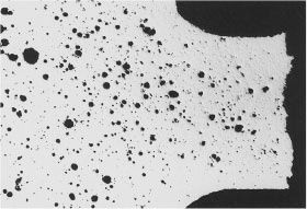
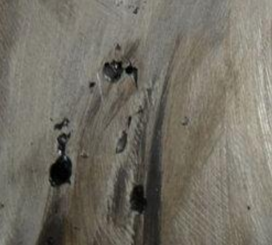
Gas Porosity Porosity is the biggest problem in die casting. There are two basic types of porosity
Gas Porosity
Shrinkage

It is critical that the individuals who are responsible for solving defects determine the kind of porosity before trying to correct it. Each takes a completely different corrective action, however they can look similar. This presentation will show examples of the two primary types of porosity. Generally, a porosity defect should be examined under 5 to 10 power magnification as a minimum. Also, it is usually better to fracture a casting to look at porosity rather than cutting it. Pay particular attention to the geometry (shape) of the porosity.


The high gas content prevents heat treating or welding because it makes the strength unpredictable. Gas porosity is round and generally smooth, although it can be flattened to some extent by pressure. The actions taken to reduce gas porosity will be reviewed, but in general they are not the same as the actions for reducing shrink porosity. There are three major sources of gas porosity for die castings:
Trapped air
Steam
Gas from lubricant
Any turbulence in the metal movement that allows some air bubbles to be trapped in the metal will mean that these bubbles will be there when the casting is solidified.
Air can be trapped in
Shot Sleeve
Gating System
Die Cavity
Gas Porosity (Shot Sleeve) By the time the metal reaches the gate, the metal flow should be atomized, however, it is vital that efforts be made to reduce turbulence as much as possible during the time frame the metal is flowing to the gate. Starting with the shot sleeve, this presentation will review potential sources of trapped air and possible corrections The first step is to maintain the same pour rate and shot delay time - this is especially important if the fill percentage is below about 50%. When the fill is less than 50%, a wave is generated by the pouring action , and this wave travels back and forth from the parting line to the shot tip.

If the wave is met by the tip as it moves forward, then extra splashing and sloshing is generated, and this captures some bubbles. However, if the tip is started forward just after the wave has been reflected from it, then the tip “chases” the wave, and this will give the best chance for minimizing air entrapment. The timer that sets the time delay between the end of pour and the start of shot will determine when the tip starts forward in relationship to this wave.

The next phase of the shot profile will be the critical slow shot speed (CSS) - this will be the speed that minimizes the trapped air during the slow shot phase. This speed is calculated from the formula:

Where k = 71 for mmps (inch system). This speed will minimize the air trapped in this portion of the shot.
The following settings should be considered important when trying to reduce air trapped in the shot sleeve. While one of these settings may not seem to be important by itself, there are interactions and it’s recommended they be repeated as close as possible once a good setting is found.
Pour rate
Delay time before shot
Slow shot acceleration
Pour hole speed
Change over point from pour hole speed to slow shot speed
Slow shot speed
Fast shot start point
We'll continue next week with die casting porosity caused by runners.
What are die casting release agents?? Die casting lubricants are designed to produce castings without defects such as soldering, staining or porosity. Too little application of lubricant can cause the part to stick to the die "Soldering." Too much can cause discoloration of the die casting "Staining." Too much lubricant in specific areas of the mold is only one of the many reasons for "Porosity." Proper use of die casting release agents combines an exact type, amount and time of application determined by careful observation and analysis.
Die Casting Process in Google News:
Continental Casting rebrands, consolidating production in Monroe City


Comments